LED Blinking Using Arduino
Last Updated :
01 May, 2024
We will interface an LED (light-emitting diode) to the Arduino UNO board. An LED is a simple diode that emits light in a forward bias. We will write an LED-blinking program on the Arduino IDE and download it to the microcontroller board. The program simply turns ON and OFF LED with some delay between them.
What is Arduino?
Arduino is an open-source, board that has a Microchip ATmega328P microcontroller on it. This microcontroller has a set of Digital & Analog input and output pins. The operating voltage of the board is 5V. It has 14 digital I/O pins & 6 Analog input pins. The clock frequency of the microcontroller is 16 MHz.
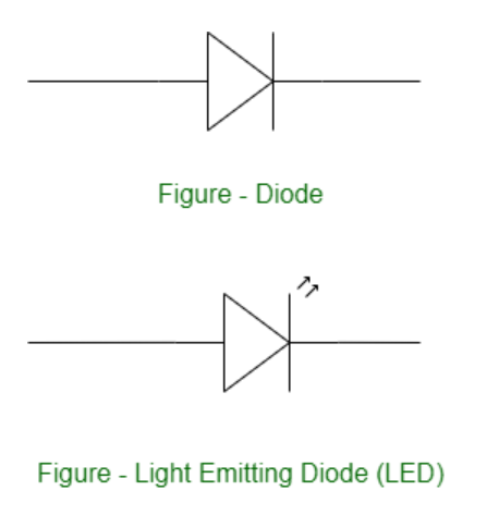
What is LED?
LEDs (Light Emitting Diodes) are becoming increasingly popular among a wide range of people. When a voltage is given to a PN Junction Diode, electrons, and holes recombine in the PN Junction and release energy in the form of light (Photons). An LED’s electrical sign is comparable to that of a PN Junction Diode. When free electrons in the conduction band recombine with holes in the valence band in forward bias, energy is released in the form of light.
Structure of an LED
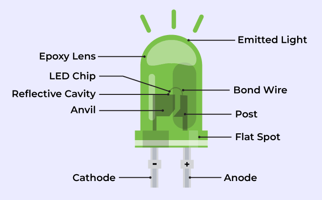
Structure of LED
The flow of charge carriers (electrons and holes) across the P-N junction drives the activity of an LED. When a forward voltage (anode positive in comparison to the cathode) is applied, electrons and holes recombine at the junction, releasing energy in the form of photons (light). The semiconductor chip is linked to external terminals known as the anode (+) and the cathode (-). The anode is linked to the P-region, and the cathode to the N-region.
Blinking an LED
Blinking an LED is an introductory Arduino project in which we control an LED using Arduino. LED blinking refers to the process of continuously turning an LED (Light Emitting Diode) and off in a repetitive pattern. It is a simple and common demonstration in electronics and microcontroller-based projects.
Working Procedure
setup() and loop() are two fundamental Arduino functions for controlling the behavior of your board. The Arduino framework automatically calls these functions, which form the foundation of any Arduino program.
The setup() function is only called once when the Arduino board boots up or is reset. Its goal is to set pin modes, initialize variables, and execute any other necessary setup tasks before the main loop begins. This function can be used to configure settings that should only be changed once over the board’s lifespan.
The loop() function is the heart of an Arduino program. After the setup() function is executed, the loop() function starts running repeatedly until the Arduino is powered off or reset. It contains the main code that performs the desired tasks, controls the board, user input. Whatever is included in the loop() function will be executed in a continuous loop, allowing the Arduino to perform its intended functions continuously.
In the code, we have declared two integers, LEDpin and delayT. LEDpin represents the pin number of the Arduino where LEDs need to be connected, and delayT is an integer variable for the delay() function. The delay() function accepts values in milliseconds.
Components Required
- 1 X LED
- 1 X Resistor, 330 Ohm
- Breadboard
- Arduino UNO R4 or earlier versions.
- Jumper wires
Components Description
- 1 X LED: We are controlling only one LED in this program.
- 1 X Resistor, 330 Ohm: For every LED, we need one current limiting resistor.
- Breadboard: A breadboard is a fundamental tool used in electronics and prototyping to build and test circuits without soldering.
- Arduino UNO R4 or earlier versions.
- Jumper wires: Jumper wires are simple electrical wires with connectors on both ends used to create connections between various electronic components or points on a circuit on a breadboard.
Arduino Code
C++
int LEDpin = 13;
int delayT = 1000;
void setup() {
  // put your setup code here, to run once:
pinMode(LEDpin, OUTPUT);
}
void loop() {
  // put your main code here, to run repeatedly:
digitalWrite(LEDpin, HIGH);
delay(delayT);
digitalWrite(LEDpin, LOW);
delay(delayT);
}
Deployment Using Arduino IDE

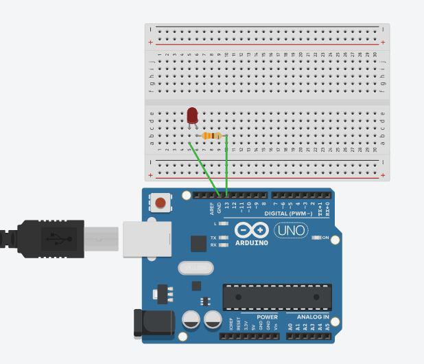
Circuit Diagram
In the circuit diagram, we used one 330-ohm resistor in series with the LED. This resistor is also called a current-limiting resistor. The Anode of the LED (the longer pin) is connected to one end of the resistor, and the cathode (the shorter pin) is connected to the ground. The other end of the resistor is connected to the Arduino pin. A step-by-step explanation is as follows:
- LED Connections: Connect the LED to the breadboard. The LED has two legs, the longer of which is the anode (positive) and the shorter of which is the cathode (negative).
- Resistor Connection: Insert one end of the resistor into the same row of the breadboard as the LED’s Anode. The resistor’s other end should be connected to the Arduino’s digital output pin.
- Ground (GND) Connection: Connect a jumper wire from the same row as the LED’s cathode to any Arduino board GND (Ground) pin. This connects the circuit to the ground of the Arduino.
The circuit is now complete. Here’s how it works:
When you upload a simple Arduino program that controls the LED, the microcontroller on the Arduino board executes the program, and the LED will blink according to the code you wrote.
Applications and Uses of LED Blinking
The LED blinking project is an important and straightforward method that can be utilized for a wide range of applications in microcontroller-based projects like :
- Security Systems: To check the status of security systems
- Warning Signals: In battery-operated devices, LED blinking can be used to indicate low battery levels.
- In Testing and debugging.
- Status Indication: LEDs can be used to indicate different states of a system. For example, in a home automation project, an LED might blink to indicate whether a device is connected to an internet network or not.
Conclusion
The Arduino LED blinking project provides a hands-on introduction to microcontrollers, hardware interfaces, and programming ideas. It serves as a foundation for more sophisticated projects and allows you to experiment with numerous Arduino features and capabilities. Whether you’re new to electronics or an expert maker, this project will help you develop crucial skills and knowledge for future Arduino-based projects.
LED Blinking using Arduino – FAQs
What is the need for interfacing LEDs with Arduino?
Interfacing LED is an important and straightforward method that can be utilized for a wide range of applications in Embedded System projects like security system, home automation etc.
What is the best way to connect an LED to a microcontroller?
A current-limiting resistor and two wires are required to connect an LED to a microcontroller. Connect longer one leg of the LED to the to the current-limiting resistor and the shorter leg to the ground. Then, connect the resistor’s other end to the microcontroller’s I/O pin.
How can I program the Arduino to blink the LED in different patterns?
You can change the loop() method in the Arduino code to make the LED blink in different patterns. For example, you can use conditional expressions (if-else) to design more sophisticated blinking patterns, or you can use numerous digitalWrite() and delay() statements to create unique on-off sequences.
In Arduino programming, how do I regulate the frequency of LED blinking?
The delay() method in the Arduino code controls the blinking frequency (the pace at which the LED turns on and off). The delay() option indicates the time in milliseconds between each on-off cycle. For example, delay(1000); will cause the LED to stay on for one second and then turn off for one second.
Share your thoughts in the comments
Please Login to comment...