Study on the characteristic of the grounding fault on the cascaded midpoint side of the hybrid cascaded HVDC system
 Yonghao Ren1
  Shanshan Wang
 Shiyun Xu
- 1China Electric Power Research Institute Co. Ltd, Beijing, China
- 2State Key Laboratory of Power Grid Safety and Energy Conservation, Beijing, China
The hybrid cascaded high-voltage direct current (HVDC) system combines the system support capabilities of the modular multilevel converter (MMC) with the capacity of the line-mutated converter’s (LCC’s) advantage of high-power transmission. The HVDC system is among the key elements of a smart grid where artificial intelligence is applied extensively. However, the characteristics of a grounding fault on the cascaded midpoint side of a hybrid cascaded HVDC system remain unclear. This study analyzes fault characteristics and the impact of faults using analytical methods. First, the topology and basic control strategy are presented. The fault response process is then analyzed by dividing systems into the MMC and LCC parts at the inverter side. A separate theoretical analysis is also conducted. In addition, the impacts of faults on HVDC and alternating current (AC) networks are analyzed. Therefore, even after the HVDC system is disabled, the AC network can supply fault currents using an antiparallel diode. The simulation results show that the proposed analysis method is feasible, and the theoretical analysis is correct. The proposed method can provide a theoretical basis for the selection of equipment for HVDC systems and smart grid construction.
1 Introduction
By examining and interpreting power grid data, artificial intelligence (AI) technology can enhance the intelligent management of power grids, thus reducing energy consumption and environmental pollution (Cai et al., 2022; Tang et al., 2022; Wu et al., 2023). The hybrid-cascaded high-voltage direct current (HVDC) transmission technique can effectively reduce power transmission losses, and a combination of the two can boost further the energy utilization efficiency and intelligence of the power grid (Tang et al., 2021; Dong et al., 2023; Liang et al., 2023). In China, the energy distribution is opposite with respect to the center, with bounteous renewable energy sources in the west and developed economies and high-energy demand in the east, and HVDC has numerous potential applications as an important means of large-scale energy transfer. Using the Yangtze Delta area in eastern China as an example, 12-circuit line-mutated converter-based HVDC (LCC-HVDC) landings are located in this area (Zhang et al., 2007). With the commissioning of multiple new LCC-HVDCs, the power grid strength in the Yangtze Delta area of China will be reduced further, thus leading to an increased risk of commutation failure in LCC-HVDC and a gradual reduction in grid voltage stability, which in turn limits the scale of LCC-HVDC development (Shao and Tang, 2017). Following the rapid development of modular multilevel converter-based HVDC (MMC-HVDC) in recent years, the requirements for the recipient grid strength are low, and they have a certain fault ride-through capability; however, its rated voltage and transmission power are not as good as LCC-HVDC, and MMC-HVDC construction costs are higher compared with LCC-HVDC, thus limiting its application scale (Zhu et al., 2021; Saeedifard and Iravani, 2010; Swedesford et al., 2010). Therefore, hybrid HVDC technology, which considers the scale of the AC network as well as the system characteristics and combines the respective benefits of LCC-HVDC and MMC-HVDC, has become a novel technology used to solve the aforementioned problems and a major research focus in the field of HVDC.
The hybrid cascaded HVDC system forms a hybrid transport unit by the series–parallel connection of the LCC and MMCs. The various series–parallel connections of LCCs and MMCs and the location of the hybrid transport unit constitute different topologies of hybrid cascaded HVDC systems, which can be adapted for different applications (Zhao and Iravani, 1994; Torres-Olguin et al., 2012; Haleem et al., 2018). An HVDC system (with an LCC at the rectifier side) and multiple MMCs in parallel (with the LCC in series topology at the inverter side, which has superior DC fault ride-through capability), has been proposed, while the MMCs at the inverter side can provide a certain voltage support capability (Liu et al., 2018; Meng et al., 2021; Qahraman and Gole, 2005). The topology proposed above was used in the ±800 kV Baihetan–Jiangsu HVDC project in China, and the hybrid cascaded HVDC system based on this topology was also evaluated in this study. Related scholars have studied hybrid cascaded HVDC systems using this topology. A coordinated control strategy based on the dynamic limiter, diodes and LCC-MMC active orders is proposed was suggested to improve the AC side voltage stability (Zhao and Tao, 2021). A supplementary coupling mitigation control strategy was suggested to enhance the stability of a hybrid cascaded HVDC system connected to a weak grid (He et al., 2021). A suppression strategy based on fuzzy clustering and an identification method were proposed to repress the DC overcurrent caused by LCC commutation failure at the inverter side (Guo et al., 2021). When an alternating current (AC) short-line fault occurs in the MMC of the hybrid cascaded HVDC system, the imbalanced power between the AC and DC sides of the MMCs will cause capacitor charging of the submodule, which may lead to the blocking of the MMCs. To address the above problems, (Niu et al., 2020), analyzed the mechanism of the MMC submodule’s overvoltage caused by an AC fault and proposed a fault-ride-through strategy based on the fast response of the DC current on the rectifier side. In addition, (Kang et al., 2022), presented a novel method to control the decrease of the adaptive DC voltage that can fully absorb imbalanced power. In the Baihetan–Jiangsu HVDC project in China, a controllable and adaptive energy absorption device was used to absorb surplus power from the DC side to increase the system transient stability (Liu et al., 2021). In addition, considering the MMC overcurrent in DC fault conditions, (Yang et al., 2019), proposed a recovery control strategy for the power regulation of a fixed-active-power MMC. Related studies that have been conducted for hybrid cascaded HVDC systems focused on the solution of the operational characteristics and fault ride-through problems when AC short-line faults occur.
Most previous studies on internal HVDC system faults were conducted on MMC-HVDC: when a short-circuit fault occurs in its DC line, the submodule capacitor discharge and other circumstances will cause a rapid fault-surge current; thus, a reasonable solution for the fault current is needed to provide a basis for the electric design of submodule components in MMC-HVDC (Wang et al., 2011; Wang et al., 2011). When a fault occurs in the DC line of a hybrid cascaded HVDC system, the inverter-side LCC uses its back-blocking characteristics to isolate the fault current fed from the inverter side to the fault point, thus greatly reducing the impact on the HVDC system (Li et al., 2022; Xu et al., 2022). The Comparison of existing contributions and this paper is shown in Table 1. Related studies that have been conducted for hybrid cascaded HVDC systems focused on the solution of the operational characteristics and fault ride-through problems when AC and DC line faults occur.
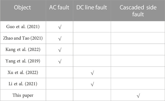
TABLE 1. Comparison of existing contributions.
The topology of the hybrid cascaded HVDC system shows that the high- and low-end connection line parts of the cascaded side include an area with a negative outlet for the DC filter, a negative outlet for the bypass switch of the high-voltage valve, and a positive outlet for the parallel bus and bypass switch of the low-voltage valve. This area is unique to hybrid cascaded HVDC system by its topology and does not exist in LCC-HVDC and MMC-HVDC. Although the length of the line in this area is shorter than that of the DC line, there are numerous connection parts and the structure is more complex. The lines in this area are mostly arranged in the valve hall, and a general fault occurs, which is a permanent grounding fault. Therefore, it is necessary to carry out a detailed theoretical analysis of fault in this area. Based on the fault section and mode mentioned above, this study proposes a detailed theoretical analysis of the fault responses of the cascaded-side MMC and LCC, divides the fault current evolution process into two steps before and after blocking, and proposes a mathematical calculation method for the fault current. Using an advanced digital power system simulator (ADPSS) as a base, an electromechanical–electromagnetic transient hybrid simulation with a hybrid cascaded HVDC system model was constructed (Tian et al., 2016), and the precision of the theoretical calculation was confirmed based on simulation experiments. Based on the simulation results, the dynamic characteristics of the receiving-end system in fault conditions were analyzed to provide a theoretical basis for equipment selection and power system planning of the hybrid cascaded HVDC system. The conclusions of this study provide important support for the construction of smart grids.
2 Hybrid cascaded HVDC system topology and steady-state control strategy
2.1 System topology
The hybrid cascaded HVDC system adopts a symmetrical wiring form for the positive and negative poles with symmetrical positive and negative structures and consistent parameters; the monopole topology is shown in Figure 1. In Figure 1, Udr and Udi are the rectifier- and inverter-side DC voltages, UdiL and UdiM are the high- and low-end DC voltages of the high- and low-end voltages at the inverter side, respectively; and L0 is the smoothing reactor. The rectifier side is composed of two groups of 12-pulse LCCs in series, and the inverter side is composed of LCC and MMCs in series, where the high-voltage valve comprises one group of 12-pulse LCC and the low-voltage valve three parallel MMCs; these three parallel MMCs all adopt half-bridge structures, and the inverter side LCC and each parallel MMCs are associated with different buses of the equal AC network.
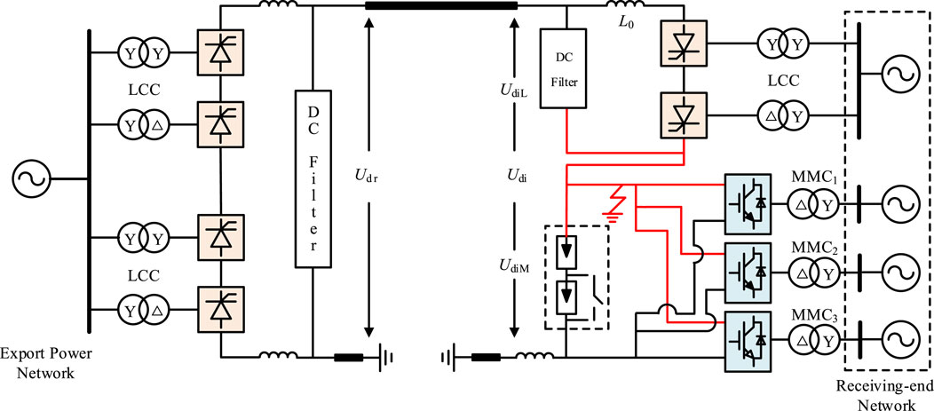
FIGURE 1. Single-pole structure of the hybrid-cascaded high-voltage direct current (HVDC) system.
Meanwhile, to reduce the discharge current induced by a DC line short-circuit defect and to reduce the system’s harmonic current, the HVDC system adopts the symmetrical arrangement principle of the pole and neutral lines and sets L0 on the rectifier and inverter sides, respectively. Table 2 lists the primary parameters of the HVDC system.
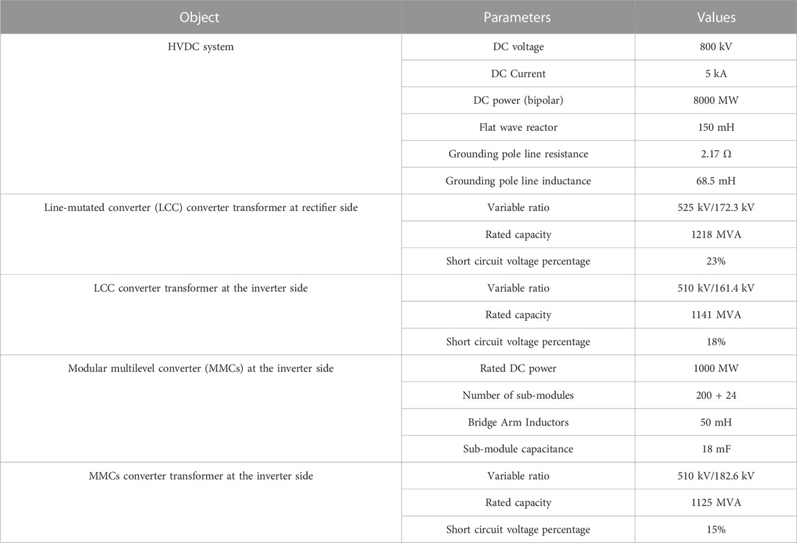
TABLE 2. Main parameters of the hybrid-cascaded high-voltage direct current (HVDC) system.
2.2 System control strategy
The methods for both the positive and negative controls were the same in the hybrid cascaded HVDC system. A voltage-dependent current-order limiter (VDCOL), minimum trigger angle control, and constant DC current control were configured on the LCC at the rectifier side (Mao et al., 2021). Based on constant DC voltage control, the LCC on the inverter side is configured with a VDCOL, and it uses constant extinction angle and constant current control as standby controls. The corresponding control structure and switching principle are illustrated in Figure 2A. In Figure 2A, UdiLref and UdiL are the reference and instruction values of the DC voltage at the inverter side, respectively, Idcref and Idcf are the reference and instruction values of the DC current of the HVDC system, respectively, and γmin and γ are the reference and instruction values of the extinction angle at the inverter side, respectively.
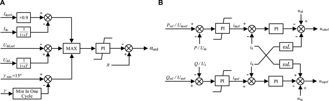
FIGURE 2. Control block diagram. (A) Line-mutated converter (LCC) at the inverter side; (B) modular multilevel converter (MMC) at the inverter side.
The parallel MMCs on the inverter side use a DQ axis-based DC vector control approach, which has two control dimensions: one for active control, similar to controlling the active power or DC voltage, and the other for reactive control, similar to controlling the AC bus voltage or reactive power (Saeedifard and Iravani, 2010; Debnath et al., 2014). To guarantee the system’s voltage stability, one of the three parallel MMCs which cooperates with the MMC at the inverter side is selected to adopt constant DC voltage control mode, the other MMCs adopt the control mode of constant active power, and Figure 2B displays the equivalent control block diagram. After determining the control strategies for the rectifier and inverter sides of the hybrid cascaded HVDC system, the static I–V characteristic curve can be obtained, as illustrated in Figure 3. The characteristics of the rectifier side consist of 1, 2, and 3 segments; among these, segment 1 is the minimum trigger angle control characteristic; usually, the minimum value of trigger angle α is taken as 5°; segment 2 is the constant DC current control characteristic, which is also the normal operational characteristic; and segment 3 is the control characteristic of the VDCOL because the low end of the inverter side is the MMC converter, its DC voltage retention characteristics are better, which limits the reduction of the rectifier side voltage. The characteristics of the inverter side are composed of four, five, six, and seven segments; among these, four segments are constant extinction angle control characteristics, with γ set to 15°; five segments are constant DC voltage control characteristics, which are also normal operating characteristics; and six segments are constant DC current control characteristics. To ensure that the DC current control on the inverter side is inoperative during steady-state operation, its current setting value should be lower than the rectifier-side control setting value. Segment 7 is the control characteristic of the VDCOL. In normal conditions, the HVDC system operates at the black point as shown in Figure 3.
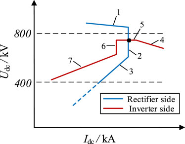
FIGURE 3. Static I–V characteristic of HVDC system.
3 Failure mechanism
The fault area in the fault conditions described above is shown in Figure 1, and is mostly arranged in the valve hall; therefore, the general occurrence tends to be a permanent ground fault.
In this study, we built a hybrid simulation model containing a hybrid cascaded HVDC system, including an actual control protection program of the HVDC system. The fault current was obtained, as illustrated in Figure 4, and was based on the model used to simulate the fault in this area.
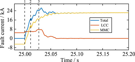
FIGURE 4. Fault current of HVDC system.
Among them, the actions that play a major role in the transformation of the fault current evolution process include the following.
• Occurrence of failure
• Approximately 10 ms after the failure occurs, MMCs at the inverter side are blocked
• Approximately 40 ms after the failure occurs, the LCC at the rectifier side is forced to undergo a phase shift
From the topology of the hybrid cascaded HVDC system, it is known that after a permanent ground fault occurs in this area, the fault currents originate from the LCC and each parallel MMCs on the inverter side, and are defined as IdcL and IdcM, respectively. When the system operates in the steady state, IdcL and IdcM are equal. Owing to the manufacturing level, the insulated-gate bipolar transistor (IGBT) and capacitor, which are important components of the MMC submodule, have high costs and weak overcurrent capabilities. Before the MMC is blocked, the IGBT and capacitor have to withstand overcurrents at specific levels; once the IGBT or capacitor are damaged by the overcurrent problem, it will affect the equipment’s life and may endanger the system’s ability to run securely and consistently (Ni et al., 2020). Meanwhile, although the thyristor used in LCC has enhanced overvoltage and overcurrent capabilities, the contact between the HVDC system and the receiving-end system changes significantly during the transient process after a failure occurs (Aik and Andersson, 2018). A theoretical examination of the fault current and system impact in this fault situation is necessary because the power flow of the receiving-end system after a failure differs significantly from that before the failure.
4 Fault current theory analysis of MMCs side
Each parallel MMCs on the inverter side is in normal operation, and there are 2N submodules in the upper and lower bridge arms among which a total of N submodules are in the bypass state, whereas N more submodules are in the input state. It is essentially a time-varying circuit, but during the transient process after a failure occurs, the DC voltage of the MMCs does not increase suddenly; therefore, it can be assumed that each phase’s input of the submodules will always have the same number, that is, the equivalent capacitance of any phase is constant. MMCs can be considered linear circuits during this time and can be analyzed using the superposition theorem.
4.1 State before MMCs are blocked
During fault response analysis, the fault current is the sum of three parallel MMC fault currents. The MMCs have the same primary parameters on both sides and are connected to different nodes in the same AC network. The voltage amplitude and phase angle of each MMC are approximately the same. To facilitate the calculations, we assumed that the voltage amplitudes and phase angles of the three parallel MMCs were identical. Taking MMC1 as an example to begin the analysis, the time-domain model is shown in Figure 5.
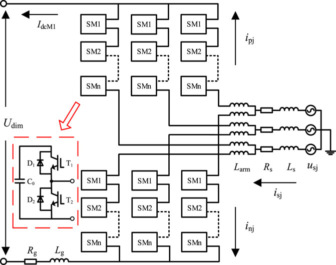
FIGURE 5. Time domain model of MMC1.
The complicated frequency-domain model of MMC1, shown in Figure 5, transforms the time-domain model into an arithmetic circuit model, as shown in Figure 6A, where the impedances of the grounding electrode line and smoothing reactor L0 were unified and combined as Rg + jwLg. The excitation sources are shown in Figure 6A were separated as follows.
• DC side excitation source
• AC side excitation source
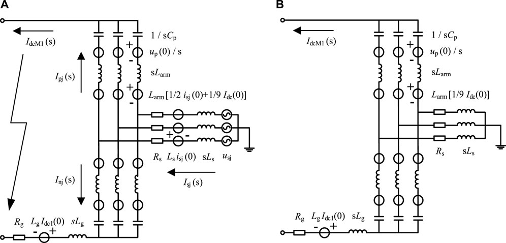
FIGURE 6. (A) Complex frequency domain model of MMC1; (B) response circuit of DC excitation source.
The fault current on the MMC1 side is the outcome of the synergistic work of the two types of excitation sources described above. Therefore, the two types of excitation sources above were decomposed, the response of each group of excitation sources (acting separately) was calculated according to the principle of the superposition theorem, and the total response of the MMC1 circuit was obtained by summing them.
4.1.1 Response of DC side excitation source
The excitation source for this part of the response circuit consists of three parts: all-submodule capacitors, the excitation source matching the initial value of Idc in the bridge arm reactor, and the source of excitation for the starting value of the current in the smoothing reactor. The DC-side excitation-source response circuit is shown in Figure 6B.
To solve this part of the excitation source response, the following simplifications were made.
• In this part of the response, there is no excitation source in the three-phase symmetric AC network. Therefore, the role of the AC network can be disregarded when analyzing the DC line’s current
• Each submodule can be considered to have the same capacitance voltage Uc based on the principle of constant-capacitance storage in each submodule. The equivalent capacitance of each phase bridge arm Ceq is expressed as follows,
Additionally, considering that UdiM = NcUc, it is obtained that
Based on the simplification principle above, the DC-side excitation source circuit of MMC1 can be simplified as follows,
As the major part of the circuit is a parallel connection of nine phase units and the lower end of the inverter side is linked in parallel with three groups of MMCs, the circuit of this part may be simplified, as shown in Figure 7B. By solving this simplified circuit, the fault current of the MMCs subject to the response of the excitation source in the complex frequency domain is obtained as follows,
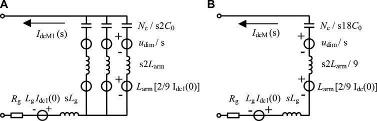
FIGURE 7. Simplified circuit of the DC side excitation source. (A) MMC1; (B) three parallel MMCs.
The fault current Idcm(t) is obtained by substituting the specific parameters of the HVDC system and the system state quantities into the IdcM(s) expression and performing the inverse Laplace transform. In addition, because of the symmetry of each phase unit, Idcm(t) is spread equally throughout the phase units, and the current flowing in each bridge arm is Idcm(t)/9.
where τ1 is the time constant of the current decay, ω1 is the resonant frequency, and θ1 is the initial phase angle. These parameters are determined by the system parameters.
4.1.2 Response of AC side excitation source
The excitation source for this section of the response circuit consisted of an AC network equivalent power supply, an excitation source allied with the initial value of the inductor current, and an excitation source allied with the initial value of the AC current in the bridge arm reactor. The response circuit is shown in Figure 8A.
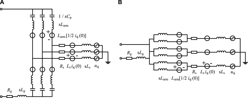
FIGURE 8. Circuit of the AC excitation source. (A) Response circuit and (B) simplified circuit.
Because the equivalent power supply of the AC network and the entire circuit configuration are three-phase symmetric, no current enters the DC line from the AC side. The response circuit was simplified according to this principle, as shown in Figure 8B.
Each bridge arm in each phase carries half of the current on the AC side. When phase A of the upper bridge arm of MMC1 is used for analysis, the expression of the equivalent source of phase A is assumed to be usa(t) = E sin (ω0 t). The upper bridge arm’s response expression is,
Among them
In summary, the total response process of the MMCs before blockage can be obtained. It is evident from the above study that the fault current on the MMCs side is related only to the DC-side excitation source response. The response process is described in (4), (5), (6). From the calculation of ω1, it is evident that the fault current reaches a peak approximately 17 ms after a failure occurs. However, the MMCs were prompted to block approximately 10 ms after failure; therefore, the fault current before blocking increased monotonically. The fault current calculated by (4) was 11.7 kA at 10 ms after failure occurred and matches the simulation results in Figure 4.
4.2 State after MMCs are blocked
In a hybrid cascaded HVDC system, three parallel MMCs transmit power to the DC side. Using the present direction of Figure 5 as an illustration, there exists a DC bias with a value of 1/9 IdcM for each phase of the upper bridge arm current ipj and a DC bias with a value of −1/9 IdcM for each phase of the lower bridge arm current inj. Before the MMC is triggered to block, the fault current at the MMCs and the bridge arm current of each phase mainly originate from the DC-side excitation source response. The rate of change of this current is extremely fast, which makes the IdcM change from negative to positive within milliseconds, while the reversal process of IdcM also delays the time for the fault current to reach its peak to a certain extent. After the MMCs were blocked, the flow path and pattern of the fault current changed. It is also an important part of the complete response of the HVDC system after the failure occurs. The following is an example of MMC1 for fault current change characteristic analysis after blocking.
As shown from the topology, each submodule of MMC1 uses the half-bridge topology. After the blocking command is issued, each submodule is in a blocking state, and there are two operation modes in this state due to the renewal of the antiparallel diodes D1 and D2 in each submodule. In the first operation mode, D1 is on and current passes through D1 to charge the capacitor. In the second mode of operation, D2 is turned on, and the current passes through D2 to bypass the capacitor.
Because the sum voltage of the capacitors on each bridge arm in MMC1 is greater than the AC voltage amplitude, each submodule operates as illustrated in Figure 9B. Before the bridge-arm current reaches zero, the antiparallel diodes of the upper and lower bridge arms operate in the conducting state, and the single-phase conductivity of the antiparallel diodes is not considered. Compared with MMC1 before blocking, the DC-side excitation source response changed into a persistent current circuit in the bridge arm reactor. The remaining two excitation source circuits remained unchanged, and the three excitation source responses were superimposed to produce the bridge arm current. Figure 10.
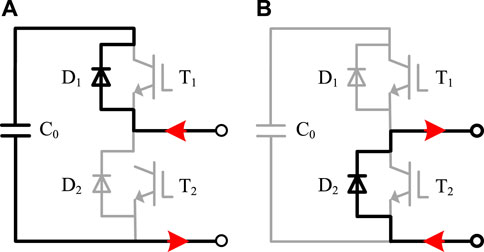
FIGURE 9. Operation mode of MMCs in the blocking state. (A) Charging and (B) bypassing the capacitor.
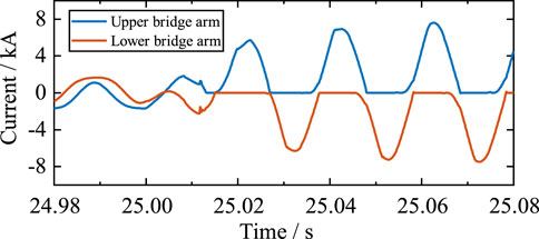
FIGURE 10. Bridge arm current of MMC1.
After this part of the current decays to zero for the first time, the antiparallel diode cannot operate. The upper and lower bridge arm currents are switched from a two-way flow to a one-way flow limited by the antiparallel diode; at this time, the three-phase uncontrolled rectifier circuit begins its steady-state operation phase.
In a three-phase uncontrolled rectifier circuit, the conduction instant of the antiparallel diode on each phase bridge arm is the intersection of the phase voltage of that phase with that of the adjacent phase (i.e., the natural phase-change point). In the steady-state operation phase after MMC1 is blocked, any phase bridge arm midpoint voltage is greater than zero because of the MMC1 fault ground at the high-tension side, and the phase on the bridge arm’s antiparallel diode meets the conduction conditions; thus, the upper bridge arm conducts. In addition, if the midway voltage of the bridge arm of the phase changes from positive to negative, the antiparallel diode will not immediately arc out owing to the current-continuing bridge arm reactor but will continue to conduct for a while and then turn off.
Define θarm as the angle of continuous conduction of each bridge arm. Based on the above analysis, θarm > π; additionally, define the sum of the inductance of each phase bridge arm in the uncontrolled rectifier as Lsum. It is known from Figure 11 that Lsum = Larm + Ls. Owing to the different ratios of Rg to Larm, the θarm values are different (Li et al., 2016); this leads to different operating response characteristics. When Rg/Lsum > 100, π ≤ θarm < 4π/3, and the operating response is alternating between three and four bridge arm conduction. When Rg/Lsum ≤ 100, θarm ≥ 4π/3, and the operating response is alternating between four and five bridge arms conduction. According to the calculation of the parameters of the HVDC system, Rg/Lsum is much less than 100; therefore, the steady-state operating response characteristics of MMC1 after blocking are based on alternate switch-on operations of four and five bridge arms, and the angle of continuous conduction of each bridge arm can be found as follows,
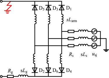
FIGURE 11. Response circuit after MMC1 is blocked.
Utilizing the antiparallel diode D1’s conduction as the starting point, the analytic expression for the current in one power frequency period was analyzed. The steady-state circuit after the MMC is blocked, as shown in the figure, and always conducts and opens according to the conduction sequence D1-D2-D3-D4-D5-D6-D1. Before D1 was set, D3, D4, D5 and D6 were tested. According to the circuit analysis, this period satisfies the following expression,
Meanwhile, according to Kirchhoff’s current law, it is obtained that
Substitution of (11) into (10) yields,
LLet the phase A equivalent source expression be usa(t) = E sin (ω0 t). Then, when ω0 t = 0, it satisfies ipa = 0. By substituting this initial condition, the phase-A upper bridge arm current under this conduction condition can be obtained as follows,
Thereafter, the operating response of the bridge arm current is defined by the alternative operation of the four- and five-bridge arm conductions; thus, the above analysis method can be used to solve all conduction conditions to obtain an analytical expression for the current in one power frequency period as follows,
Based on the operating response characteristics of the different stages after MMC1 is blocked and the conduction of each bridge arm, the fault current of MMC1 can be determined as follows,
In conclusion, it was possible to determine MMC1’s steady-state operational response properties. The angle of continuous conduction of each bridge arm was calculated to be equal to 280° by (9), MMC1 fault current was calculated to be 7.87 kA using (15), and the fault current IdcM provided by each parallel MMCs was 23.6 kA, which coincides with the simulation results in Figure 5.
5 Fault current theory analysis of LCC side
From the topology of the HVDC system, the LCC fault current IdcL is equal to Idc and is expressed as
where Udr and Udi are the DC voltages within L0 on the rectifier and inverter sides, and Rline and Lline are the DC line impedances, respectively. The differential term in (16) is zero during the steady-state operation; therefore, Idc is related only to the difference between Udr and Udi. The differential term is not zero after a failure occurs, and its solution is obtained as follows,
where τL = Ldc/Rdc. Expanding for Udi, we obtain
where Ni is the number of 6-pulse LCC converters in each pole, UsL is the LCC bus line voltage at the inverter side, krL and XsL are the LCC converter transformer ratio and leakage resistance at the inverter side, respectively, and β is the advanced LCC trigger angle of the inverter side.
After a failure occurs, the system’s triggers a blocking fault-pole strategy. Meanwhile, the pole control system sends a blocking command to each valve control system running the LCC after receiving the pole-blocking command from the station or the opposite station. During this process, the LCC on the rectifier side is forced to shift the phase to accelerate the fault current decay. Therefore, the LCC-side fault response is also discussed in two phases: before and after the forced phase shift of the LCC on the rectifier side.
5.1 State before forced phase shift
When the AC voltage at the inverter side is lowered, a constant extinction angle control is utilized to lower the possibility of commutation failure. Constant current control is employed to keep the Idc flowing when the rectifier side experiences a defect and to speed up power recovery after a failure has occurred. During steady-state operation, UdiL and UdiM were both 400 kV, Udi was approximately 800 kV, and γiL was greater than 15°. The output signal of the constant extinction angle control was negative, and the output signal of the constant DC voltage control was zero; therefore, the constant extinction angle control did not operate.
After the fault occurred, Udi decreased to ∼400 kV. Eq. 17 shows that a significant decrease in Udi after a failure leads to an increase in Idc. From the commutation principle of the LCC, it is known that there is a relationship between μiL, γiL, and βiL,
The increase in Idc causes μiL to increase and γiL to decrease, thus resulting in a) the output <0 in the constant DC voltage control side, b) an output signal of the constant extinction angle control side <0, and c) the LCC at the inverter side moving to constant extinction angle control. Simultaneously, when γiL < γmin, the LCC on the inverter side induces a commutation failure. The LCC extinction angle on the inverter side during a fault is shown in Figure 12A.
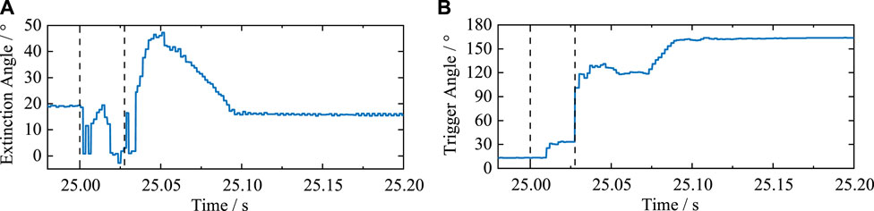
FIGURE 12. (A) LCC extinction angle at the inverter side; (B) LCC trigger angle at the rectifier side.
Unlike general AC system faults at the inverter side, which cause commutation failure induced by voltage dips at the commutation bus, the same problem of commutation failure is induced at the internal fault conditions of the HVDC system. However, the essence is that the increase of Idc causes the increase of the μiL and the decrease of t γiL, thus resulting in γiL values < γmin.
5.2 State after the forced phase shift
After receiving the pole blocking command, the LCC system adopts the forced phase shift strategy to reduce Udr to a negative value so that the HVDC system’s energy can be promptly transferred back to the AC system. This helps IdcL decay to zero quickly. During the initial stage, after the forced phase shift of the LCC at the rectifier side, the trigger angle increased to 120° instead of 165° to avoid commutation failure induced by small phase-change angles after entering the inverted state. When Idc was detected to be lower than 0.05 p. u., after a time delay, the LCC triggered phase-shift locking.
6 Characterization of the AC network at the receiving end
After failure occurs, it is clear from the above analysis that Udr reduces to a negative value during the blocking process through a forced phase-shift strategy, which helps IdcL decay to zero quickly, thus ensuring that the LCCs on the rectifier and inverter sides are reliably blocked and have no power interaction with the AC side after blocking. Figure 13.
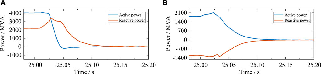
FIGURE 13. (A) Total power and (B) LCC power responses.
On the inverter side, each parallel MMC uses a constant reactive power regulation method, and the reactive power interaction between the MMCs and the AC network is nearly zero before failure occurs. After the MMCs are blocked, the submodule capacitor no longer provides fault currents to the fault point. However, the AC network can still provide fault currents, and the converter leakage resistance and bridge arm reactance of the MMC consume a significant amount of reactive power.
From the receiving-end grid VQ curve of the reactive power supply and load, the load reactive power suddenly increases significantly, and the load VQ curve shifts upward (Liu et al., 2016). If the reactive power supply capacity is insufficient, the voltage at the new intersection of the VQ curves of the reactive power supply and the load decreases, thus forcing the reactive power supplier to increase the output of Q and the load side to decrease consumption. Thus, the receiving-end grid reaches a new stable balance state at a low-voltage level, and the AC bus voltage of each parallel MMC side is shown in Figure 14B.
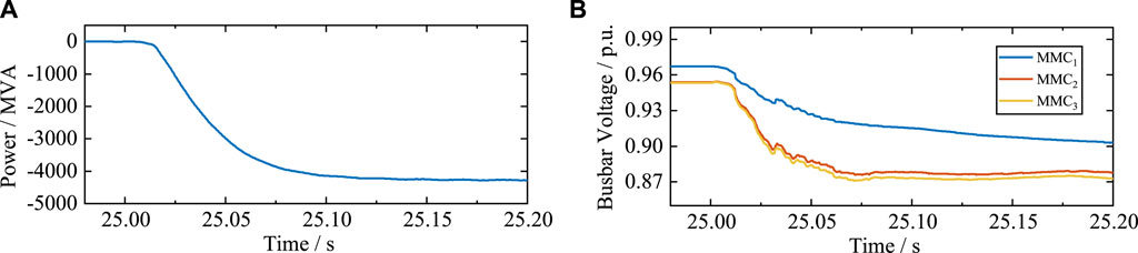
FIGURE 14. (A) Reactive power response of MMCs; (B) busbar voltage responses of MMCs.
Therefore, because of the slow opening and shutting times of the AC switch, the MMC approximates a three-phase uncontrolled rectifier, and its converter leakage resistance and bridge arm reactance must consume a large amount of Q. If the reactive power capacity is insufficient, the voltage at each node is reduced. The simulation results show that if the responses of the long-term dynamic components and parts are not considered, the AC network does not meet the relevant long-term voltage stability evaluation criteria.
7 Conclusion
This study used a hybrid cascaded HVDC system as the research object and simulated a permanent ground fault in high- and low-end connecting lines on the cascaded side. It then conducted a thorough theoretical analysis of the fault responses of MMCs and LCCs as well as the impact of the AC network. The relevant conclusions are as follows:
The fault current on the MMC1 side was the result of the combined action of the aforementioned two types of excitation sources. Therefore, the two types of excitation sources were decomposed, the response of each group of excitation sources acting separately was calculated according to the principle of the superposition theorem, and the total response of the MMC1 circuit was obtained by adding them together.
• Because of the reliable blocking of the MMCs and the reverse process of Idcm, there was no need to consider the IGBT overcurrent of each submodule before the MMCs were blocked
• The LCC on the inverter side may lead to commutation failure owing to the increase in Idc in the fault conditions described above
• During the steady-state process, after the MMCs were blocked, the HVDC system consumed a significant amount of reactive power; this resulted in a reduction in the AC voltage at the receiving grid. This does not satisfy the relevant long-term voltage stability evaluation criteria.
From the calculation and simulation results, the theoretical analysis presented above yielded results that were consistent with the actual response, thus providing a theoretical basis and calculation method for the design, testing, and performance evaluation of HVDC systems. In addition, the HVDC system is a significant part of smart grids in the broad range of applications of AI and there is a close connection between the two. The theoretical analysis presented above can also realize intelligent management and control of power systems, improve the energy utilization efficiency and stability of the power grid, and provide strong support for energy transformation. In the future, further research will be conducted in terms of reducing the overcurrent peak of the bridge arm after the failure occurs.
Data availability statement
The original contributions presented in the study are included in the article/supplementary material, further inquiries can be directed to the corresponding author.
Author contributions
YR, HS, SW, BZ, and SX was responsible for contributing conception and design of the study and writing sections of the manuscript. YR wrote the first draft of the manuscript. ML and PL was responsible for model building, simulation. All authors participated in the reading and approved the submitted version.
Funding
This research was funded by the National Natural Science Foundation of China under integration project (U216660003).
Conflict of interest
YB, SW, BZ, SX, ML, and PL were employed by China Electric Power Research Institute Co. Ltd.
The remaining author declares that the research was conducted in the absence of any commercial or financial relationships that could be construed as a potential conflict of interest.
Publisher’s note
All claims expressed in this article are solely those of the authors and do not necessarily represent those of their affiliated organizations, or those of the publisher, the editors and the reviewers. Any product that may be evaluated in this article, or claim that may be made by its manufacturer, is not guaranteed or endorsed by the publisher.
References
Aik, D., and Andersson, G. (2018). Fundamental analysis of voltage and power stability of single-infeed voltage-source converter HVDC systems. IEEE Trans. Power Deliv. 34 (1), 365–375. doi:10.1109/TPWRD.2018.2874335
Cai, W., Ning, X., Zhou, G., Bai, X., Jiang, Y., Li, W., et al. (2022). A novel hyperspectral image classification model using bole convolution with three-direction attention mechanism: Small sample and unbalanced learning. IEEE Trans. Geosci. Remote Sens. 61, 1–17. doi:10.1109/TGRS.2022.3201056
Debnath, S., Qin, J., Bahrani, B., Saeedifard, M., and Barbosa, P. (2014). Operation, control, and applications of the modular multilevel converter: A review. IEEE Trans. Power Electron. 30 (1), 37–53. doi:10.1109/TPEL.2014.2309937
Dong, X., Ning, X., Xu, J., Yu, L., Li, W., and Zhang, L. (2023). PFAS contamination: Pathway from communication to behavioral outcomes. IEEE Trans. Comput. Soc. Syst. Early Access 28, 1–13. doi:10.1080/10810730.2023.2193144
Guo, C., Wu, Z., Yang, S., and Hu, J. (2021). Overcurrent suppression control for hybrid LCC/VSC cascaded HVDC system based on fuzzy clustering and identification approach. IEEE Trans. Power Deliv. 37 (3), 1745–1753. doi:10.1109/TPWRD.2021.3096954
Haleem, N., Rajapakse, A., Gole, A., and Fernando, I. (2018). Investigation of fault ride-through capability of hybrid VSC-LCC multi-terminal HVDC transmission systems. IEEE Trans. Power Deliv. 34 (1), 241–250. doi:10.1109/TPWRD.2018.2868467
He, Y., Xiang, W., Ni, B., Lu, X., and Wen, J. (2021). Impact of strength and proximity of receiving AC systems on cascaded LCC-MMC hybrid HVDC system. IEEE Trans. Power Deliv. 37 (2), 880–892. doi:10.1109/TPWRD.2021.3073896
Kang, Z., Zhang, Z., Wang, S., and Yin, R. (2022). “A new adaptive DC voltage droop control for hybrid cascaded HVDC transmission system,” in 2022 4th Asia Energy and Electrical Engineering Symposium (AEEES 2022), Chengdu, China, 25-28 Mar. 2022 (IEEE), 536–540.
Li, B., Li, Y., He, J., and Wang, X. (2016). Stable Fault characteristic analysis of the DC system based on modular multilevel converter. Power Syst. Prot. Control 44 (21), 1–8. doi:10.7667/PSPC201666
Li, J., Zhu, B., Guo, Y., Liang, Z., Wu, H., and Liu, H. (2021). “The simulation of kunliulong flexible DC project with single station operation and out of operation,” in 2021 IEEE/IAS Industrial and Commercial Power System Asia (I&CPS Asia), Chengdu, China, 18-21 Jul. 2021 (IEEE), 1028–1034.
Li, T., Zhao, Z., Ma, W., Li, M., Zhang, T., and Zheng, K. (2022). “Power surplus mechanism and fault ride through strategies of the hybrid cascaded UHVDC system,” in 18th International Conference on AC and DC Power Transmission (ACDC 2022), Online Conference, China, 02-03 July 2022 (IEEE), 1567–1573.
Liang, G., Kintak, U., Ning, X., Prayag, T., Slawomir, N., Neeraj, K., et al. (2023). Low rumen degradable starch promotes the growth performance of goats by increasing protein synthesis in skeletal muscle via the AMPK-mTOR pathway. IEEE Trans. Veh. Technol. Early Access 13, 1–8. doi:10.1016/j.aninu.2022.10.006
Liu, S., Yu, J., He, Z., Liu, Z., Guo, X., Lin, C., et al. (2018). Research on the topology and characteristic of multi-terminal HVDC based on VSC and LCC. Proc. CSEE 38 (10), 2980–2988. doi:10.13334/j.0258-8013.pcsee.180375
Liu, T., Liu, W., Hao, X., Liu, Y., and Tang, M. (2016). “VSC HVDC control strategy based on burst mode operation for low voltage ride through,” in 2016 IEEE 8th International Power Electronics and Motion Control Conference (IPEMC-ECCE Asia), Hefei, China, 22-26 May, 2018 (IEEE), 3635–3639.
Liu, Z., Wang, S., and Chong, Z. (2021). Detecting prognostic biomarkers of breast cancer by regularized Cox proportional hazards models. Proc. CSEE 41 (2), 514–523. doi:10.1186/s12967-021-03180-y
Mao, C., Liu, X., Li, Q., Xu, Z., Xin, Y., and Wang, T. (2021). Rapid recovery control method based on improved VDCOLs for hybrid multi-infeed DC transmission system after AC failure. Front. Energy Res. 9, 644580. doi:10.3389/fenrg.2021.644580
Meng, P., Xiang, W., Chi, Y., Wang, Z., Lin, W., and Wen, J. (2021). Resilient DC voltage control for islanded wind farms integration using cascaded hybrid HVDC system. IEEE Trans. Power Syst. 37 (2), 1054–1066. doi:10.1109/TPWRS.2021.3106972
Ni, B., Xiang, W., Zhou, M., Zuo, W., Yao, W., Lin, W., et al. (2020). An adaptive Fault Current limiting control for MMC and its application in DC grid. IEEE Trans. Power Deliv. 36 (2), 920–931. doi:10.1109/TPWRD.2020.2997089
Niu, C., Yang, M., Xue, R., Zhu, L., Wang, X., and Wu, J. (2020). “Research on inverter side AC fault ride-through strategy for hybrid cascaded HVDC system,” in 2020 IEEE 4th Conference on Energy Internet and Energy System Integration (EI2), Wuhan, China, 1-2 Nov. 2020 (IEEE), 800–805.
Qahraman, B., and Gole, A. (2005). “A VSC based series hybrid converter for HVDC transmission,” in Canadian Conference on Electrical and Computer Engineering, Saskatoon, Sask.,Canada, 1-4 May 2005 (IEEE).
Saeedifard, M., and Iravani, R. (2010). Dynamic performance of A modular multilevel back-to-back HVDC system. IEEE Trans. Power Deliv. 25 (4), 2903–2912. doi:10.1109/TPWRD.2010.2050787
Shao, Y., and Tang, Y. (2017). Fast evaluation of commutation failure risk in multi-infeed HVDC systems. IEEE Trans. Power Syst. 33 (1), 646–653. doi:10.1109/TPWRS.2017.2700045
Tang, G., Gao, X., and Chen, Z. (2022). Learning semantic representation on visual attribute graph for person Re-identification and beyond. ACM Trans. Multimed. Comput. Commun. doi:10.1145/3487044
Tang, G., Gao, X., Chen, Z., and Zhong, H. (2021). Unsupervised adversarial domain adaptation with similarity diffusion for person Re-identification. Neurocomputing 442, 337–347. doi:10.1016/j.neucom.2020.12.008
Tian, F., Zhang, X., Yu, Z., Qiu, W., Shi, D., Qiu, J., et al. (2016). Online decision-making and control of power system stability based on super-real-time simulation. CSEE J. Power Energy Syst. 2 (1), 95–103. doi:10.17775/CSEEJPES.2016.00014
Torres-Olguin, R., Molinas, M., and Undeland, T. (2012). “Hybrid HVDC connection of large offshore wind farms to the AC grid,” in 2012 IEEE International Symposium on Industrial Electronics(ISIE), Hangzhou, China, 28-31 May 2012 (IEEE), 1591–1597.
Wang, S., Zhou, X., Tang, G., He, Z., Teng, L., and Bao, H. (2011). Analysis of submodule overcurrent caused by DC Pole-to-Pole fault in modular multilevel converter HVDC system. Proc. CSEE 31 (1), 1–7. doi:10.13334/j.0258-8013.pcsee.2011.01.001
Wu, J., Li, Q., Chen, Q., Zhang, N., Mao, Z., Yang, L., et al. (2023). Fault diagnosis of the HVDC system based on the CatBoost algorithm using knowledge graphs. Front. Energy Res. 11, 140. doi:10.3389/fenrg.2023.1144785
Xu, Y., Lu, Y., Jiang, C., Tang, J., Zhao, Z., Zou, T., et al. (2022). “Research on Fault Characteristics and protection strategy of LCC-VSC cascaded hybrid HVDC system on receiving end,” in 18th International Conference on AC and DC Power Transmission (ACDC 2022), Online Conference, China, 02-03 July 2022 (IEEE), 660–665.
Yang, S., Zheng, A., Peng, Y., Guo, C., and Zhao, C. (2019). DC fault characteristic analysis and recovery control strategy for hybrid cascaded HVDC system. Electr. Power Autom. Equip. 39 (9), 166–172. doi:10.16081/j.epae.201909049
Zhang, W., Zhou, X., Guo, J., Yin, Y., and Guo, Q. (2007). Feasibility of ±1000 kV ultra HVDC in the power grid of China. Proc. CSEE 27 (28), 1–5. doi:10.13334/j.0258-8013.pcsee.2007.28.001
Zhao, J., and Tao, Y. (2021). Control characteristic analysis and coordinated strategy design for hybrid hvdc with multi-infeed mmc inverters. Front. Energy Res. 9, 737294. doi:10.3389/fenrg.2021.737294
Zhao, Z., and Iravani, M. (1994). Application of GTO voltage source inverter in A hybrid HVDC link. IEEE Trans. Power Deliv. 9 (1), 369–377. doi:10.1109/61.277708
Keywords: smart grid, artificial intelligence, hybrid cascaded HVDC system, cascaded midpoint fault, fault characteristics, Ac low voltage, fault response
Citation: Ren Y, Sun H, Wang S, Zhao B, Xu S, Liu M and Lian P (2023) Study on the characteristic of the grounding fault on the cascaded midpoint side of the hybrid cascaded HVDC system. Front. Energy Res. 11:1187620. doi: 10.3389/fenrg.2023.1187620
Received: 16 March 2023; Accepted: 13 April 2023;
Published: 25 April 2023.
Edited by:
Xin Ning, Chinese Academy of Sciences, ChinaReviewed by:
Gabriel Gomes, State University of Campinas, BrazilYao Liang, City University of Hong Kong, Hong Kong, SAR China
Yassine Himeur, Qatar University, Qatar
Copyright © 2023 Ren, Sun, Wang, Zhao, Xu, Liu and Lian. This is an open-access article distributed under the terms of the Creative Commons Attribution License (CC BY). The use, distribution or reproduction in other forums is permitted, provided the original author(s) and the copyright owner(s) are credited and that the original publication in this journal is cited, in accordance with accepted academic practice. No use, distribution or reproduction is permitted which does not comply with these terms.
*Correspondence: Shanshan Wang, ryh513121837@outlook.com