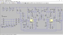
You have the DC servo connected to the non-inverting input of the LM3886. I'd visit that in the simulator before cutting a PCB.
±35 V is right at the limit of the 7818 and 7918 regulators' capabilities. I'd allow for some margin or at least somehow guarantee by design that the supply voltage never exceeds ±35 V even during startup or mains voltage excursions.
Don't forget the Thiele network (L || R) on the output and the not-so-optional stability components (Cc, Cf, and Rf2 in the data sheet). You'll get better performance near clipping with these parts in the circuit.
Looks solid otherwise. Make sure to choose a resistor type with a low temperature coefficient for the two 0.1 Ω ballast resistors.
Tom
You have the DC servo connected to the non-inverting input of the LM3886. I'd visit that in the simulator before cutting a PCB.
±35 V is right at the limit of the 7818 and 7918 regulators' capabilities. I'd allow for some margin or at least somehow guarantee by design that the supply voltage never exceeds ±35 V even during startup or mains voltage excursions.
Thank you for your input!
I am very new to this.
Any suggestions on simulator software?
And any recommendations on how to make sure the supply voltage not to exceed more than 35V? Will 56R resistor in series solve that?
Thank you!
New version with balanced and unbalanced inputs.
Even though it is a simple circuit that I had in my mind, it turned into this huge behemoth with 32 capacitors, 30 resistors, 4 chips, 5 diodes, and 2 regulators. Never even though I will approach project like this before lol.
Initially, the idea was to have two parallel LM3886 working together - since they will drive 4 Ohm loads at 35V easier. Plus, I already have Antek AN-4225 transformer - that is 400VA power in there, 25-0-25V secondary. Should be able to handle two channels of two LM3886 in parallel easy (I think).
This amp is to be loaded with Klipsch RP-5 speakers - https://www.klipsch.com/products/rp-5-floorstanding-speaker. I also have balanced outputs from my preamp - Rolls RM67 - https://rolls.com/product/RM67. Even though outputs from the preamp are balanced, I also wanted to leave an option to be able to plug in simple RCA inputs in the future. So, there it is, my first attempt at engineering to solve the real world problem.
Hope my findings in this direction helps the diy community.
You could pre-regulate the inputs to those 78/79 regs with a zener and series resistor. Set the zener voltage comfortably below their max.
Alternatively you could change to shunt regs (TL431 would work) and then you'll get around the maximum input voltage restriction and only have to contend with the dissipation in the series Rs feeding the shunts.
If I were you I'd add a cap to GND after the series 56R, some regs don't much like being fed from a high-ish impedance. Oh and 56R won't reduce the input voltage to those regs by very much, perhaps a volt or two.
Last edited:
Interesting as I've played around with similar using an LM3886 as a simulation (actually a parallel pair) but with a different (a discrete) amp as one half of the bridge. If its a bridge design then you could consider single rail? The load is still DC coupled between the two halves of the bridge.
Would have to be LTspice for me.

Definitely.
I seem to be missing something in the diagram in post #1 because it looks like both halves of the bridge are identical and both sides take the same input signal... am I having a moment here and not seeing something obvious
Any suggestions on simulator software?
Would have to be LTspice for me.

I'd visit that in the simulator before cutting a PCB.
Definitely.
I seem to be missing something in the diagram in post #1 because it looks like both halves of the bridge are identical and both sides take the same input signal... am I having a moment here and not seeing something obvious
I seem to be missing something in the diagram in post #1 because it looks like both halves of the bridge are identical and both sides take the same input signal... am I having a moment here and not seeing something obvious
I might've missed a resistor or two there lmfao. This is my first design with no background in electrical engineering whatsoever....
Sim it first as @tomchr suggests before you descend to such a level of detail I think  LTSpice is a simulator you can download for free though there's no model in it for LM3886. But to evaluate the servo you can just use an ordinary opamp in place of the LM3886.
Hello everyone!
Looking for input on the schematic I have came up! I'm new to audio diy so I'm not expecting that it is perfect.
Power input is +-35V
Thank you!
View attachment 1030264
Pardon me for asking, but whats the purpose of paralleling two chips?
Did you find one not to be adequate? You need double current? Tough speaker load?
Why not three in parallel? Its been published and tested. Or six.
Or chip with extra bjt on output to boost the current.
Or just adequate discrete design.
I seem to be missing something in the diagram in post #1 because it looks like both halves of the bridge are identical and both sides take the same input signal... am I having a moment here and not seeing something obvious
I might've missed a resistor or two there lmfao. This is my first design with no background in electrical engineering whatsoever....
Nope, it's me
A FET opamp like a TL072 (or TL071) would normally be a first choice for a servo because the 5532 (and other bjt opamps) will have a large offset of their own unless you balance the input bias currents.I am also considering swapping that NE5532 from the servo circuit with TL072. What do you guys think?
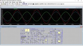
Well it seems to work OK. I can see a couple of things that might need altering on the original such as R8/R31 and C6/C31 which are duplicates. Basically it all works.
I'll post the .asc but it will not work without the LM3886 model. I can post that model and symbol but I find models in LT the most difficult part and I suspect they still won't run because the netlists will be tied to my PC and user name. That said its not difficult to recreate the required files from the model (and before someone asks I can't remember... its in the LT thread I think)
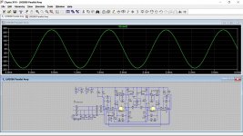
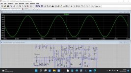
Full output into 4 ohm:


Attachments
Higher output current. I cover the tradeoffs here: https://neurochrome.com/pages/output-powerPardon me for asking, but whats the purpose of paralleling two chips?
Both were great opamps in their time. And they're still fine opamps, but more modern options with better performance exist. I'm a big fan of the LME49720/LM4562 in audio circuits. OPA1612 springs to mind as well, though it can be a bit finicky to get to work well. OPA2134 is a nice option too.I am also considering swapping that NE5532 from the servo circuit with TL072. What do you guys think?
Due to the input bias current these opamps are not so suitable for DC servo service. The TL072 would work but it has a JFET input so the input offset current is still high-ish (5 nA, worst case). It's older technology so its worst case DC offset is ±5 mV. That's fine for a power amp but you can get better performance for the same price with a more modern opamp. OPA2277 and OPA2197 spring to mind. OPA202 looks interesting as well.
Any simulator will do, but you'll find better support for TI products in TI's simulators: TINA-TI and PSpice for TI. Both are free downloads from TI.Any suggestions on simulator software?
Many folks here use LTspice from Linear Tech (now part of Analog Devices). I've used that in the past for simulating vacuum tube circuits and circuits that included LT parts. I simply cannot get over the UI. It's so 1990s UNIX/Solaris that it makes my stomach churn. That said, it's a fine simulator. It's geeky enough to require you to type in SPICE commands to get the simulations running. That'll throw off most beginners but it's nice for those of us who grew up with SPICE in the late 80s early 90s.
This terminology will come in handy:
DC simulation: Simulates the DC operating point. Useful for determining node voltages at steady-state and useful to determine whether the circuit will bias up correctly. I use DC sims for other things as well, but those two are the major ones.
AC simulation: Simulates the frequency response of the circuit. Beware that the AC simulation usually doesn't care about the DC operating point. This means that you can have a simulation that shows a nice frequency response but doesn't actually work.
Transient simulation: Simulates voltages as function of time. This is handy if you want to look at the step response, for example. It's also required if you want to look at distortion. Do beware that distortion is not always included in the circuit models. The LM3886 model from TI does not include distortion, for example. So it's very possible to get excellent distortion performant in simulation but garbage performance in reality. Also note that the transient simulation starts with a calculation of the DC operating point. If that fails to converge you won't get any transient results. So go back to the DC sim to figure out what went wrong. And finally: You can force the transient simulation to start with all voltage sources set to 0 V. This is handy for simulating startup. It can also be helpful in getting the DC simulation to converge and the transient sim to run.
Start by simulating something simple like an RC network or a resistive divider.
Design the power supply so that it doesn't. Or use a regulator such as the LM317 (LM337 for the negative rail). It's a floating regulator so it only cares about the difference between input and output.And any recommendations on how to make sure the supply voltage not to exceed more than 35V? Will 56R resistor in series solve that?
BTW: Instead of having two differential receivers you can just connect the inputs to the LM3886 in parallel and drive them with one receiver. Also, currently your differential bridge is not balanced and has a gain of 0.5 V/V. You probably want to address that.
Tom
Sim it first as @tomchr suggests before you descend to such a level of detail I thinkLTSpice is a simulator you can download for free though there's no model in it for LM3886. But to evaluate the servo you can just use an ordinary opamp in place of the LM3886.
Will do
(and before someone asks I can't remember... its in the LT thread I think)
This is how to do it for those interested. Post 3183 and follow the link in #3187.
https://www.diyaudio.com/community/...from-beginner-to-advanced.260627/post-6913604
You should end up here:
https://www.diyaudio.com/community/...from-beginner-to-advanced.260627/post-6287652
and be sure to see this a couple of posts down:
https://www.diyaudio.com/community/...from-beginner-to-advanced.260627/post-6287660
Looks like it will take me some time to get up to speed in terms of sim software.
Meanwhile, I just edited the schematics to include TL072 for servo and removed second NE5532 buffer.
Balanced/unbalanced input circuitry idea was copied from Small signal audio design by Douglas Self. As he writes:
"in the world of hifi balanced signals are at twice the level of the equivalent unbalanced signals, and so the balanced input must have a gain of 1/2 or -6dB relative to the unbalanced input to get the same gain by either path. This is done here by increasing R6 and R7 (circuit below) to 20 kOhm."
"Two compromises in this circuit - noise performance in unbalanced mode is worse than for the dedicated unbalanced input because R9 is effectively in the signal path and Johnson noise. Secondly, the impedance of the unbalanced input cannot be very high because it is set by R8 - cannot be increased because all four resistors R6, R7, R8, and R9 will need to be increased proportionally - that degrades noise performance."
I wonder if I should increase the gain for LM3886 to compensate for balanced input -6dB difference?
Again, I'm hoping to get into circuit sims to maybe find answer for that...
Again, I'm hoping to get into circuit sims to maybe find answer for that...
This might get you interested (and started) in simulation. This file should just click and run in LTpsice and uses opamps in place of the LM3886. The gain structure is the same.
Click my signature line to see how to get started.

Attachments
- Home
- Amplifiers
- Chip Amps
- LM3886 in parallel with servo circuit build attempt
